

Calculating the Position by Independent Measurement System#
Overview#
This document explains the calculation of rigid body position by using the reading of independent measurement system (IMS).
Displacement Sensors#
The following figure shows the location of each pair of displacement sensors, located at the A ring. There are 4 rings in the M2 mirror: A, B, C, and D. The 6 tangential actuators are located at A ring with a displacement sensor aside. The sensors are A1, A2, A3, A4, A5, and A6 as labeled in the figure. Every sensor measures two values: \(\theta_z\) and \(\Delta_z\).
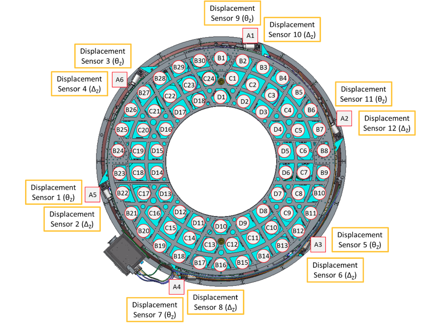
Identification of displacement sensors on M2 cell assembly.#
Displacement Vectors#
The measurement of displacement sensors gives two vectors: \(\vec{d}_{\theta}\) and \(\vec{d}_{\Delta}\). Each vector has 6 elements from sensors A1 to A6. The vector of displacement (\(\vec{d}\)) is a combination of \(\vec{d}_{\theta}\) and \(\vec{d}_{\Delta}\) as the following:
Parameters#
There are two important elements in the calculation: the offset and the transformation matrix.
Offset#
The offset (\(\vec{d}_{\text{offset}}\)) is the value of displacement sensors recorded when the M2 is at the home position. This vector might need to be updated if the default home position is changed. See the value in disp_ims.yaml.
Transformation Matrix#
The transformation matrix (\(\mathbf{M}_{\text{trans}}\)) is a 6x12 matrix to transform the readings of IMS to rigid body position \((x, y, z, r_{x}, r_{y}, r_{z})\). See the matrix in disp_ims.yaml.
Calculation#
The following equation calculates the rigid body position:
Appendix#
Define the scaling factors (\(s_{r}\) and \(s_{\theta}\)), we have:
Therefore, the transformation matrix, \(\mathbf{M}_{\text{trans}}\), is \(\text{pinv}(\mathbf{M})\). We have \(s_{r} = 0.001\) mm/um and \(s_{\theta} = 1/3600 \times \pi/180 \times R_{M}\) mm/arcsec, where \(R_{M}=(1781.04^{2} + 9.52^{2})^{1/2}\) mm. The R1 and Z1 positions are used in the calculation of mirror’s radius \(R_{M}\).